First, Assume A Perfectly Spherical Aerialist
One of the great things about the scientific process, is the little surprises one stumbles across. A few weeks ago I was a designing a specialized piece of circus rigging to drop one half of a 100Lb ladder. It has a quick release mechanism, which when activated, drops the ladder 4′ mid performance. Now, how to figure out how strong the components should be?
This sounds like a job for math! Awesome. Using the following shock loading formula, we can arrive at an approximate resultant force:
Fshock = ((Dfall * W) / Dstop) + W
Damn. This just creates more questions. How to calculate the stopping distance, Dstop?
This turns out to be really, really complicated. The material you are hanging from, what it’s anchored too, the length of the material in question, the temperature of the material, etc, etc. All these things can affect your answer. Some of those variables have such a small effect that we can just outright ignore them. Others are very important. Two important ones are the cross sectional area, and the modulus of elasticity of the rope you are hanging from. (Thanks Internet!)
Pulling a formula from page 38 of Stage Rigging Handbook by Jay Glerum, I run a calculation for 48”, 0.25 diameter aircraft cable and get 6730Lbs on a free fall drop of 4′. Holy crap! All that from 50Lbs? You bet. Where does it all come from? The short stopping distance is the culprit. If you look carefully at our first, simplified formula you will notice that as stopping distance approaches 0, the shock load approaches infinity. Somewhere along that curve the intuition and expectations we derive from our day to day experiences stop matching reality, and as one of my favorite authors once said, reality doesn’t go away when you stop believing in it.
So what do we do?
Well, as mom used to say, there’s no substitute for experimental data. I decided to just measure these shock loads and work backwards from there. Enter the load cell.
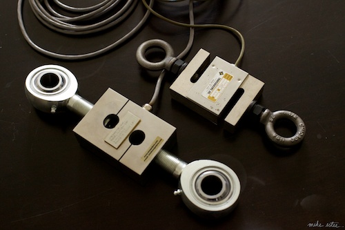 10K & 3K S-Beam load cells.
If money was no object, I would just go out and purchase one of these bad boys. It’s about the same price as a used motorcycle. Money was an object for me, so I went a different route and decided to roll my own.
Digging around on eBay I found that S-beam (hanging type) load cells are around 50-150$ used. They rarely come with the bolts, which can be more expensive than the cell itself. Time to put in another McMaster order. Make sure you check the threading specs before you bid, as the eyebolts usually have a higher TPI than ones you find at your local rigging supply. I also needed matching jam nuts to keep them from slipping over time.
The load cell itself is a wheatstone bridge strain gauge. A great article on how they work can be found here. The short of it is, you’ll need an amplifier to get anything useful out of them. You can build one for around 30$ in parts and what ever your time is worth, or you can buy one from Solid Motion for ~100$, which is what I did. Their product is excellent, noise free, and comes in a snazzy package. Make sure the load cell amp matches the load cell you purchased. Mine was a 3mV/V so I ordered the SGA01-333-100 to match.
That raises another question. How big a load cell do I need? The first one I got was a 10,000Lb model. I figured that this was the highest load I would ever want to test for, so why not start there? Well, there are a few problems with this. First, to actually safely handle that load the cell must be mounted with ball joint rod-ends. Big ones, costing 50$ each. Ouch. The reason for this is that the S-beam cell is only designed to handle on-axis tensile & compression loads, the ball joints keep the rod-ends and the cell aligned.
The other reason a 10K cell is not the best choice for observing dynamic aerial loads is that strain gauges usually have a minimum reading. That is, you have to load them above their minimum range before they start working. This number is usually 1% of the maximum load. Let me see, 1% of 10,000 is… most of the weight of your average aerialist. Drat. After learning this I got another smaller 3K load cell. It registers a minimum load of 30Lbs. Much more reasonable. I’ll just save the 10K for breaking things.
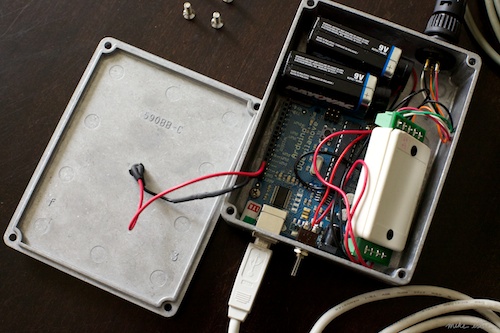 Arduino, amplifier, and batteries.
So now I had the cell and amp. Next up, I needed a way to visualize what the heck was going on. Time for the twin powers of Arduino and Processing. Two great tools that go great together. Using an Arduino Duemilanove board I got from the totally awesome and amazing folks at Adafruit Industries. I hooked up the amplifier to the analog port and started coding. First problem: the Arduino A/D has a lower resolution than we need, and a much lower reference voltage, 1.1, 2.4V or 5V vs the amplifiers 10V output. Again, for the kinds of loads I was seeing with actual humans this still wasn’t a problem. With a 5V reference I can get a 1500Lb range. Perfect for my purposes. I just need to remember to not blow out the A/D on the Arduino by putting more than 1.5K on the cell…
I’ve made all the code for this available here: https://github.com/mikest/loadcell-vis. There’s a download link there if you’re not into using git. You will also need to grab the Processing & Arduino environments from their respective sites.
Processing made short work of the visualization side of the equation. The Arduino board sends a continuous serial stream of timestamped reading to the sketch, which draws them onscreen in realtime. Awesome. Now I can measure how much force this ladder makes when dropping 4 feet….
932Lbs?
Well that’s a dozen frozen tunas away from the 6730Lbs I calculated before! What the heck? Turns out that most things in the real world are kind of squishy. The 50Lbs of sand bags I used have a fair amount of elasticity in the nylon straps and canvas case. The cable I used was amsteel, not stainless aircraft cable. It has a lot more stretch. All of this adds up to 5798Lbs1 worth of shock being absorbed elsewhere. After a couple minutes of bungie pack tuning, I cut that down to 400Lbs. Down right comfy, and as the kids say these days, made of awesome.
However, what would be made of even more awesome would be all this information overlaid on top of slow motion video, as it’s awfully hard to make sense of all this without seeing the performance at the same time.
First, we’ll need a camera. If I had my pick, I’d go with the Phantom Gold. Sadly, it’s somewhere north of 100,000$, so instead I opted for the more reasonable Casio EX-FH100. Mine was 250$, and worth every penny. It does 120fps at 640×480, which is frankly amazing.
For that price though, you don’t get timecode. I had to come up with a somewhat uglier method of syncing the data and video. I started with a few assumptions, the first being that I was going to have to do some manual work in there somewhere. Next, the recordings would all be short. Under 5 minutes at the max, so drift would be less important. Finally, ultimate accuracy is less important than “useful to an aerialist”. So with that in mind, I came up with a system of syncing the video and the data stream.
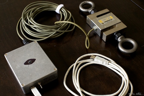 The Whole Enchilada.
The system works by strobing a really bright LED on the box which is turned on for a certain number of frames at the start of the data acquisition. While the LED is on, it marks which frames it is on for in the data stream. To record a session, I point the camera where it can see the LED and the performer. Next I open the loadcell_client.pde sketch in processing, and start the camera. Then, when everything is ready, I press the M key to start logging the load cell data. The LED strobes for a brief moment and the performance is recorded. I press the M key again to stop and save the data stream out to a file, and stop the camera.
Now I have two files: a trace-0.txt file, and a CIMG001.AVI movie file of the performance. Using the next processing sketch, loadcell_render.pde, I rename the files trace.txt and video.avi and put them in the loadcell_render/data/ folder. Once the sketch is started it will load up the movie. Using the arrow keys I advance the frame forward and backward until we see the LED first start to turn on. (If you hold down shift it goes 10 frames at a time.) Once I’ve found the first moment the LED starts to flash in the video I press G key to start the render. The processing sketch will go through every frame of the movie and draw the data graph. When enough of the movie is rendered out, I press SPACE to stop and save the movie to the out.mov file. (Thank you Dave Bollinger for the SteppedMovie.java code, which makes file writing possible!)
Here’s what the results look like2…
So yeah. That’s probably useful for something. Next up, I’m working on making the system wireless and a little more… svelte. The cable dangling from the top anchor really gets in the way. It’s also not really long enough, which is why I have to, uh, tuck my feet there on the landing…
Of course, since the entire system is open source, you could build it into something else. One area I’m interested in exploring is using the output load data in realtime to create processing scripts which can project reactive patterns and graphics over the performance. In any event, given a perfectly spherical aerialist, it will produce interesting results.
1 Yes, yes, I know that’s not quite right… we’re actual moving the work from 271 joules around.
2 Thanks to Jaron and the KAC for letting me run this science experiment!</p>