Paper Robots, Part 2
Paper linkages are pretty neat, but ultimately if I want these little parts to do anything I need to figure out how to make them move. Not being force based actuators, servos are the wrong answer, but they’re cheap and I have piles of them. Because of their ubiquity, supporting hardware is easy to find as well. For example, these excellent low cost, high channel count PWM servo driver boards from Pololu.
This platform of parts for position based actuators is a large part of what perpetuates their continued use in hobby robotics. There really isn’t a platform for force based actuators yet, and we won’t see real accelerated innovation in force based control systems until they’re a bit more ubiquitous. That’s what platforms do. They lower the cost of entry, and allow a larger number of people to try out new ideas quicker than before. Until then, it’s going to be servos the whole way down.
I tried two designs. The first was an attempt to keep with my self-imposed goal of making linkages fold up from a single flat pattern. There are a bunch of paper folding tricks that can allow one to create arbitrarily complex geometries in paper, but they require back folding which tends to weaken the joints a bit. You can see an example of this folding near the mini grommets:
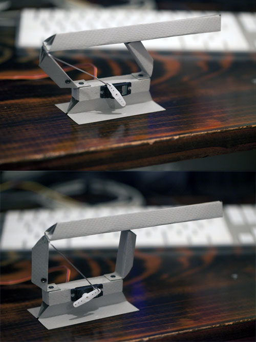 Servo Swing Arm.
The back fold creates an extension in the flat pattern that creates more clearance at the expense of increased bulk. This particular design worked out ok, but the back fold was very fragile when loaded from one direction. The distance from the servo arm and the plane of motion was also a bit of a problem. The servo arm should ideally be centered under the upper swing arm linkage. Offset as it was, it still generated a fair amount of force and a good travel distance, but I wouldn’t expect it to last very long before it tore itself apart.
Confident that I could handle up/down reasonably well, I set about tackling the forward/back motion for the leg. I kept the same servo mount pattern for the up/down link, but moved the grommet bearing farther out for more leverage. For the front/back servo I decided that folded single pattern robots, while technically challenging, don’t really add a lot to the experience. So, with that ideal cheerfully abandoned, I was free to come up with a more robust general solution to mounting servos in paper.
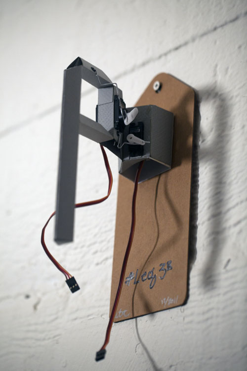 Two degree swing arm.
The front/back servo is mounted in a little friction fit cup with lip tabs that glue to a hole cut out of the side panel. Sort of like a tiny paper cardboard box. As long as the direction of force runs parallel-ish to the mounting surface the servo will stay put. The mounting tabs also add a bit of rigidity to the side wall. So far so good.
While the paper servo mount cup was a success, the attachment for the arm linkage was a complete failure. I didn’t bother to design the paper-clip servo arm linkage up front, and tacked it on afterwards. As a consequence the lower edge where the paper clip attached started to bend and fall appart almost immediately. Connecting the servo arms to the paper links in a robust and secure method isn’t something I’ve found a good general solution too. The paper-clip is pretty strong, but it presses on the paper with a small surface area which needs to transfer to a larger surface area on the linkage. We’ll try to find some solutions to those ideas next time…
Ultimately, the goal of these objects is to try and find a way to make a really, really low cost force actuated motion system. To that end, I thought I’d play around with force and see how these linkages and construction methods behave under load.
I’ve been making all my previous legs with 140Lb charcoal sketch paper. For this next one, I wanted to see how well cardboard would work. Corrugated cardboard is really strong, and when creased, flexible. It’s an awesome construction material, so long as it never gets wet.
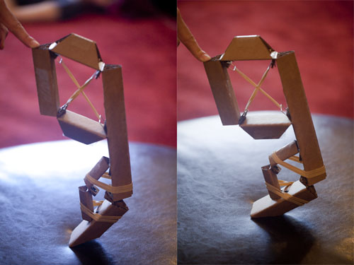 Spring legs.
I used 4mm cardboard, which has a much larger bend radius than 0.2mm card stock I had been previously using. This necessitated scaling up the leg quite a bit. I made a double swing arm, with a lower leg. Mostly to try try out two different hinge attachment methods, but also ‘cause it looks cool 😉 Important stuff. The larger swing arm uses a pair of grommets, paper clip hooks, and large rubber bands to set the force. It works beautifully, and the paperclip rubber band holders let me adjust the tension easily.
The lower swing arm sets the rubber bands from the outside, and uses a single grommet. It’s too delicate to hold together very well at this scale. The leg itself is pretty fun to play with, and can jump surprisingly high. It’s completely passive of course, but it gives me an idea of how responsive the linkage itself could be. Because the leg weighs almost nothing on its own, it can move really fast.
There are a couple of directions I want to go from here. Maybe some simple force based actuators. In the mean time, maybe I’ll make some jumping coffee tables.